skip to Main Content

Why Choose Hydraulic Check Valves?

Why Choose Hydraulic Check Valves?

Hydraulic check valves may look small, but they control an important direction inside a fluid power system. They allow oil to move forward while resisting reverse flow. That simple action can protect pumps, stabilize actuators, and prevent unwanted cylinder movement.

Hydraulic engineer John Watton has said, “A check valve is simple, but its application is not.” This observation reflects field experience. A valve that works well on a clean test bench may behave differently beside a noisy pump, a long hose, or contaminated oil. Selection requires more than matching port size. Engineers must examine cracking pressure, flow capacity, response time, leakage, temperature, and installation position.

The right valve can reduce pressure shocks and protect downstream components. It can also support load holding when the circuit loses pressure. Small detail. Major consequence.

Still, no check valve solves every hydraulic problem. Incorrect sizing may create excessive pressure loss. Poor filtration may cause leakage. A weak spring may delay closing, while a strong spring may restrict flow unnecessarily. These trade-offs deserve honest attention.

This guide explores why hydraulic check valves remain widely used across mobile equipment, industrial machinery, presses, and material-handling systems. It connects technical principles with practical selection advice. Readers will see how internal poppets, springs, seals, and flow paths affect real performance. The goal is not to promise a perfect component. It is to help engineers choose a reliable one for the actual circuit.
Why Choose Hydraulic Check Valves?

Hydraulic Check Valves: Definition and Basic Operating Principles

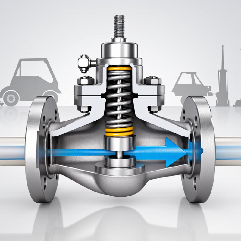
Hydraulic check valves are one-way devices that control fluid movement inside a hydraulic circuit. They permit flow in the intended direction and resist reverse flow. This basic function protects pumps, separates pressure zones, and helps prevent unwanted actuator movement. The valve opens when inlet pressure exceeds outlet pressure plus its cracking pressure. When flow reverses, the closing element returns to its seat. The passage then becomes sealed.

Common designs use a spring-loaded poppet, ball, or guided spool. Each design creates different pressure loss, response speed, and sealing performance. A spring-loaded poppet often provides quick closure. A ball design may suit simpler circuits. Selection depends on flow rate, operating pressure, fluid cleanliness, and temperature.

Small details matter. A valve rated for high pressure may still perform poorly with excessive contamination.

During installation, technicians should follow the flow arrow and inspect connection surfaces carefully. Incorrect orientation can stop the circuit or damage nearby components. In field inspections, a common lesson is that valve problems are not always obvious. The pump may sound normal while a cylinder slowly drifts because of internal leakage or poor seating. This is easy to miss.

Proper sizing requires checking cracking pressure and allowable pressure drop at the real flow rate. A low cracking pressure is not always better. Some circuits need stronger closing force to prevent backflow. Others need minimal resistance for efficient movement. Testing with a pressure gauge can reveal behavior that specifications alone may hide.

Key Types of Hydraulic Check Valves and Their Structural Differences

Why Choose Hydraulic Check Valves?

Hydraulic check valves stop fluid from returning through a circuit. This protects pumps, actuators, and pressure-sensitive components. Their internal structures determine response speed, leakage control, and pressure loss. A ball check valve uses a spherical element against a seat. It is compact and responds quickly, but contamination can prevent tight closure. A poppet check valve uses a guided plug and spring. Its stronger sealing surface suits higher pressures, although the spring creates a cracking pressure.

A swing check valve pivots a disc away from the flow path. It produces low resistance in larger lines, but it needs suitable mounting and steady flow. A pilot-operated check valve adds a pilot piston or control passage. This structure can hold a cylinder securely until hydraulic pressure releases it. It is useful for load holding, yet incorrect pilot pressure may cause delayed opening. In practice, engineers should compare flow direction, leakage limits, response time, and available installation space. No design is perfect. Even a well-selected valve may perform poorly with dirty oil or a damaged seat.

Tips: Check the arrow on the body before installation. Keep the fluid clean and confirm the cracking pressure. Inspect fittings for misalignment, especially near compact manifolds. A pressure test under real operating conditions can reveal problems that bench testing misses. Small details matter.

Why Choose Hydraulic Check Valves?

Key types of hydraulic check valves and their structural differences

Hydraulic check valves allow fluid to flow in one direction and block reverse flow. Ball and poppet valves use a simple spring-loaded closing element, while spool valves guide a cylindrical element through a sleeve. Pilot-operated check valves add a pilot port and control piston, allowing the main valve to open when a release signal is applied.

How Hydraulic Check Valves Control Flow and Prevent Backflow

Hydraulic check valves allow fluid to move in one intended direction. A spring-loaded poppet opens when inlet pressure exceeds cracking pressure. When pressure reverses, the poppet seats quickly and blocks the return path. This simple response protects pumps, actuators, and filled lines from unwanted movement.

In a cylinder circuit, backflow can let a raised load drift or make an actuator retract unexpectedly. In a pump discharge line, reverse flow can spin the impeller backward and intensify water hammer. The U.S. Department of Energy’s Improving Pumping System Performance sourcebook reports that pumping systems may consume 25–50% of a facility’s electricity. Preventing backflow does not erase that cost, but stable flow helps operators control it. The Hydraulic Institute and Europump Pump Life Cycle Costs guide identifies energy as a major lifecycle expense, often near 40%.

Sizing still matters. A valve with excessive cracking pressure wastes energy and creates heat. A valve that closes too slowly may permit damaging pressure transients. Field checks should compare flow rate, fluid viscosity, mounting direction, and reverse-pressure requirements. Clean oil helps. Contaminated oil does not. That detail gets missed. Pilot-operated designs can reduce shock in larger circuits, but they require correct pilot pressure and maintenance. No valve is perfect. Poor installation can defeat a good design.

Major Benefits of Using Hydraulic Check Valves in Fluid Systems

Why Choose Hydraulic Check Valves?

Major Benefits of Using Hydraulic Check Valves in Fluid Systems

Hydraulic check valves control fluid movement in one direction. They close when pressure reverses, helping protect pumps, cylinders, and control lines. In practical maintenance work, this action can prevent pressure shocks and unwanted cylinder drift.

Their main benefit is reliable flow control. A correctly sized valve supports stable actuator movement and reduces backflow losses. It can also maintain pressure in a clamped or lifted load. Less leakage often means less heat, lower energy waste, and longer component life. Small details matter.

These valves suit many compact hydraulic layouts. Their straightforward design makes inspection easier than complex control devices. Technicians can check cracking pressure, contamination, spring condition, and sealing surfaces during service. However, check valves are not automatically efficient. Incorrect sizing may cause excessive pressure drop or delayed movement. It is easy to select one by port size alone. That approach can fail. Flow rate, oil viscosity, temperature, mounting direction, and working pressure all require review. Filtration remains important. Even a dependable valve can stick when particles damage its seat. Maintenance records also improve fault diagnosis and system reliability.

Selection Criteria for Reliable Hydraulic Check Valve Performance

Why Choose Hydraulic Check Valves?

Reliable hydraulic check valve performance begins with selection, not installation. Match the valve’s pressure rating to the system’s maximum pressure, including pressure spikes. A 10% safety margin is often useful, but it should not replace testing. Flow capacity matters too. An undersized valve creates pressure loss, heat, and slower actuator movement. The 2024 NFPA State of the Industry report identifies energy efficiency and equipment uptime as continuing priorities for fluid power users.

Cracking pressure deserves close attention. A valve requiring excessive spring force may restrict low-pressure return flow. A valve set too lightly may allow reverse leakage. Use ISO 4413 guidance for risk control, and record ISO 4406 fluid cleanliness codes during commissioning. ISO 4406 measures particles at 4, 6, and 14 micrometres. That detail is small. Its effect is not. In field service, contamination often damages sealing surfaces before the valve reaches its rated cycle life. The rating looks convincing, yet the application may still fail.

Tips: Compare pressure-drop curves at the actual flow rate. Check fluid compatibility, temperature range, mounting direction, and seal material. Test cold-start performance. It is easy to overlook. Keep inspection records, then review them after the first 500 operating hours. A perfect specification sheet cannot predict every pulsation, installation error, or unexpected fluid condition.

Why Choose Hydraulic Check Valves? - Selection Criteria for Reliable Hydraulic Check Valve Performance

Selection Criterion Typical Engineering Data Why It Matters Recommended Verification
Valve Function Standard check, pilot-operated check, or hydraulically controlled check The valve type determines whether reverse flow is blocked only or intentionally released by a pilot signal. Confirm the required flow direction, load-holding function, and pilot-control sequence.
Cracking Pressure Common selectable values: approximately 0.25, 0.5, 1, 2, and 5 bar (3.6, 7.3, 14.5, 29, and 72.5 psi) A lower cracking pressure reduces restriction, while a higher value can help prevent unwanted circulation or movement. Compare the spring setting with the minimum available system pressure and the required cracking differential.
Maximum Working Pressure Many industrial hydraulic check valves are rated around 210–420 bar (3,000–6,000 psi); the exact rating depends on design and size. The pressure rating must withstand continuous operating pressure, transient spikes, and any trapped pressure. Select a rating above the maximum measured system pressure, including calculated shock and surge conditions.
Flow Capacity Typical industrial sizes may handle roughly 5–300 L/min (1.3–79 US gal/min), depending on port size and valve construction. Undersizing increases pressure drop, heat generation, noise, and the risk of unstable operation. Use the manufacturer’s flow-versus-pressure-drop curve at the actual operating flow rate.
Pressure Drop A well-sized valve is commonly selected to keep normal pressure loss below about 0.5–2 bar, subject to the circuit design. Lower pressure drop improves actuator speed, energy efficiency, and oil temperature control. Check pressure-drop data for both forward flow and reverse-flow shutoff conditions.
Reverse Leakage Poppet-style valves can provide very low internal leakage; spool-style valves generally permit more leakage clearance. Low leakage is essential for load holding, position retention, and prevention of actuator drift. Review the stated leakage limit and test method; do not assume “zero leakage” without a specified test condition.
Fluid Compatibility Mineral hydraulic oils are widely supported; water-glycol, phosphate-ester, biodegradable, and other fluids require material confirmation. Incompatible fluids can damage seals, reduce lubrication, corrode components, or shorten service life. Match the fluid type, additives, cleanliness level, and seal material to the valve specifications.
Viscosity Range Many hydraulic components operate within approximately 10–400 mm²/s (cSt), with a narrower optimum range often specified by the design. Viscosity that is too high increases pressure loss; viscosity that is too low can increase leakage and reduce lubrication. Evaluate the minimum cold-start and maximum operating viscosity, not only the nominal oil grade.
Operating Temperature A common hydraulic operating range is approximately −20°C to +80°C (−4°F to +176°F), but seals and fluid may limit the actual range. Temperature affects viscosity, seal life, spring performance, and the stability of internal clearances. Verify both ambient and fluid temperature limits, including cold starts and heat-soak conditions.
Port Size and Connection Common connections include threaded, cartridge, subplate, flange, and hose or tube interfaces; nominal sizes often range from small instrument ports to large high-flow ports. Correct connection geometry prevents installation errors, leakage, excessive velocity, and flow restriction. Confirm thread standard, port orientation, sealing method, mounting envelope, and required installation torque.
Response and Stability Spring-loaded poppet valves usually provide direct closing action; pilot-operated designs add controlled opening and closing behavior. Stable movement helps prevent chatter, pressure spikes, vibration, and premature seat or spring wear. Assess dynamic response at minimum, nominal, and maximum flow, especially in long or high-inertia lines.
Contamination Tolerance Fine clearances and sealing seats can be affected by particles; filtration is normally required for reliable hydraulic operation. Contamination may cause the valve to stick open, leak internally, or fail to close fully. Specify the required ISO 4406 cleanliness level and ensure filtration is suitable for the valve’s sensitivity.
Maintenance and Inspection Preferred features include accessible inspection points, replaceable seals, clear flow-direction markings, and serviceable internal parts. Straightforward maintenance reduces downtime and helps preserve leakage and pressure performance. Include inspection of leakage, cracking pressure, contamination, seals, and mounting connections in the maintenance plan.

Note: The values shown are typical engineering reference ranges rather than universal limits. Final selection should be based on the valve datasheet, actual circuit conditions, applicable safety requirements, and verified pressure-drop and leakage data.

Back To Top