skip to Main Content
Global buyers need more than a familiar name when selecting hydraulic components. They need dependable performance, clear documentation, and support across different operating environments. Continental hydraulic valves attract attention because they are associated with practical hydraulic control and established industrial applications. However, a purchasing decision should begin with verified requirements, not assumptions.
A suitable valve must match pressure, flow rate, fluid type, temperature, port configuration, and control method. These details affect machine response, energy use, and maintenance intervals. For example, a valve working in a dusty agricultural machine may face different demands than one installed in a clean factory line. Buyers should examine technical drawings, model numbers, compatibility data, and replacement availability before approving an order. Small differences matter.
Real experience also shows that product quality alone does not guarantee a successful installation. Incorrect sizing can create noise, leakage, slow movement, or unnecessary downtime. No valve is perfect. Even a trusted product needs correct commissioning and regular inspection. Continental hydraulic valves may be a strong option for global projects, but buyers should confirm current specifications with qualified distributors or the manufacturer. Regional inventory, shipping conditions, warranty terms, and technical response times also deserve attention. These factors are easy to overlook.
This guide explores why international buyers consider Continental hydraulic valves for demanding equipment. It reviews performance, application suitability, service support, and purchasing risks. The goal is not to promise universal results. It is to provide a balanced basis for comparison, helping engineers and procurement teams make decisions with greater confidence.
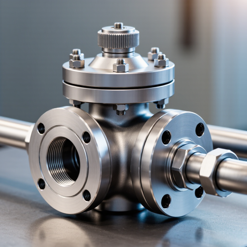
The term Continental hydraulic valves commonly describes industrial valves used in hydraulic systems across continental and global markets. They control oil direction, pressure, and flow. A pump sends pressurized fluid through ports, while the valve guides that fluid toward an actuator. The actuator then moves a cylinder or motor.
The working principle is practical. A spool valve shifts inside a machined body, opening selected passages. A poppet valve seals tightly against its seat. Relief valves protect circuits when pressure rises beyond a set limit. Flow-control valves regulate actuator speed.
In an excavator, a small lever movement can redirect oil within seconds. That response must be smooth and predictable.
Global buyers should examine pressure ratings, port dimensions, seal materials, and operating temperatures. Metric and imperial connections are not always interchangeable. Installation errors happen. Clean hydraulic oil also matters because tiny particles can scratch spools and cause internal leakage. During sourcing, I would request test records, dimensional drawings, and traceable material information. A valve may look suitable on paper yet perform poorly with contaminated oil or the wrong seal. Field experience suggests checking replacement availability before approving the design. That step is easy to overlook.
Modern hydraulic valve performance depends on control accuracy, response speed, and contamination tolerance. In field commissioning, pressure-compensated spools help maintain stable flow when loads change suddenly. Proportional solenoids also allow smoother speed control than basic on-off designs. Servo technology delivers finer positioning, but it demands cleaner oil and tighter maintenance routines.
Small errors matter.
Digital valve controllers now support CAN-based communication, sensor feedback, and remote diagnostics. These features help operators identify pressure spikes, coil faults, and slow response before production stops. The International Energy Agency’s World Energy Outlook 2023 reports that industry uses roughly 37% of global final energy. Efficient flow control can therefore reduce wasted power, especially in high-cycle machinery. However, efficiency claims need measured data. A valve with advanced electronics may still perform poorly when sizing, filtration, or installation is wrong.
Tips: Check the rated flow at your real operating pressure. Review ISO 4413 safety requirements and use ISO 4406 cleanliness codes during oil testing. Record response time, leakage, and temperature during acceptance tests. Do not trust catalogue figures alone. Actual results can vary.
A practical selection should also consider modular manifolds, corrosion-resistant materials, and replaceable seals. These details simplify service across different climates. I have seen compact valves fail early because heat dissipation was ignored. That lesson is easy to miss. Performance is not only a component feature; it is a system result.
Global buyers need more than a pressure rating. They need evidence that hydraulic valves remain safe across different machines, climates, and maintenance practices. ISO 4413 defines safety principles for hydraulic systems, including pressure control, hose protection, and energy isolation. ISO 12100 also requires documented risk assessment before machinery enters service. These standards give buyers a practical screening framework.
Quality begins with controlled production. Incoming steel should have traceable material certificates. Each valve should receive pressure, leakage, and functional testing. Test records should identify the batch, operator, and calibrated equipment. The 2022 ISO Survey recorded more than 1.26 million ISO 9001 certificates worldwide. That figure shows the scale of formal quality management, but certification alone does not prove valve performance. The proof is practical.
Global compliance also depends on safety design. A valve may meet rated pressure on a clean test bench, yet fail after contamination or incorrect installation. This is where suppliers must provide clear port markings, installation limits, maintenance intervals, and emergency guidance. IEC 61508 principles can support functional-safety evaluation where control failure creates serious risk. Small details matter.
Buyers should request declarations, test reports, material traceability, and change-control records. They should also verify whether regional requirements affect electrical interfaces, documentation, or machine integration. No valve is perfect. A strong supplier admits operating limits and explains them clearly. That honesty is often more valuable than another marketing claim.
ISO 4406 hydraulic-fluid cleanliness code
Clean hydraulic fluid supports reliable valve response, limits abrasive wear, and helps maintain consistent safety performance. The chart shows the ISO 4406 particle-count bands for particles equal to or larger than 4 μm(c), expressed as the maximum particles per millilitre in each code range.
Reference: ISO 4406:2021, Hydraulic fluid power — Fluids — Method for coding the level of contamination by solid particles.
Global buyers should judge hydraulic valves by operating evidence, not catalog appearance. Pressure comes first. Match maximum pressure, flow rate, response time, and duty cycle to the machine’s real workload. A 2024 Grand View Research analysis projected the global hydraulic valves market to grow at about 4.8% annually through 2030. That growth increases choice, but it also increases selection risk.
Fluid compatibility matters. Check seals, temperature limits, contamination tolerance, and viscosity ranges. ISO 4413 emphasizes safe hydraulic-system design, including pressure control and energy isolation. Buyers should also verify test certificates, traceability, and conformity with local requirements. Service access is equally practical. A valve may perform well, yet become expensive when replacement parts travel across borders. Local technical support can reduce downtime. Total cost is more useful than purchase price.
Tips: Ask for pressure-drop curves, endurance-test results, and clear failure-mode data. Confirm whether the valve defaults open, closed, or neutral after power loss. Review warranty terms carefully. Do not guess. A common mistake is choosing a compact valve without checking heat buildup. That decision may pass a factory test, but fail inside a dusty cabinet. No checklist is perfect; field conditions often expose assumptions that laboratory data cannot.
| Evaluation Factor | Why It Matters to Global Buyers | Practical Reference Data or Benchmark | Documents or Evidence to Request | Priority |
|---|---|---|---|---|
| Rated Pressure | The valve must safely handle the system's continuous and peak hydraulic pressure without excessive deformation or leakage. | Common industrial ranges: 210 bar and 315 bar. The selected rating should exceed the system's maximum working pressure with an appropriate safety margin. | Technical datasheet, pressure-rating chart, proof-test information, and application limitations. | High |
| Flow Capacity | Correct flow capacity helps maintain actuator speed, reduce pressure loss, and prevent unnecessary energy consumption. | Compare rated flow in L/min at a stated pressure drop, commonly shown at 5 bar or 10 bar depending on valve design. | Flow-pressure curves, pressure-drop data, and recommended maximum flow. | High |
| Valve Configuration | Spool arrangement, number of positions, actuation method, and center condition determine how the hydraulic circuit operates during neutral and emergency states. | Typical directional options include 2-position or 3-position designs, with spring-centered, detented, manual, pneumatic, hydraulic, or solenoid actuation. | Hydraulic symbols, circuit diagrams, dimensional drawings, and port-function descriptions. | High |
| Fluid Compatibility | Seal and body materials must be compatible with the specified hydraulic fluid to avoid swelling, hardening, corrosion, or premature failure. | Common mineral-oil systems use petroleum-compatible seals; water-glycol, phosphate-ester, and biodegradable fluids may require different materials. | Fluid compatibility chart, seal-material specification, and maximum fluid-temperature limits. | High |
| Operating Temperature | Ambient and fluid temperature affect viscosity, seal life, solenoid performance, and pressure capability. | Many standard hydraulic applications operate approximately from -20°C to +80°C, but the actual range depends on seals, fluid, electronics, and duty cycle. | Operating-temperature range, storage-temperature range, viscosity limits, and derating information. | High |
| Contamination Tolerance | Hydraulic contamination is a major cause of sticking spools, wear, leakage, and shortened service life. | A cleanliness target around ISO 4406 18/16/13 is commonly used for general industrial hydraulic systems; sensitive proportional systems may require cleaner fluid. | Recommended filtration level, cleanliness requirements, and installation instructions. | High |
| Internal Leakage | Low leakage improves actuator holding, positioning accuracy, energy efficiency, and system stability. | Leakage limits are design-specific and should be stated as a measured flow at defined pressure, fluid viscosity, and temperature rather than as a general claim. | Leakage test method, maximum permitted leakage, and test conditions. | High |
| Port and Mounting Standards | Standard interfaces simplify installation, replacement, maintenance, and cross-border sourcing. | Common interfaces include ISO 228-1, ISO 6149, SAE J514, CETOP/ISO mounting patterns, and other region-specific thread standards. | Port-thread specification, mounting pattern, interchangeability information, and complete dimensional drawing. | High |
| Electrical Compatibility | Solenoid valves must match the machine's voltage, frequency, connector type, power rating, and control architecture. | Common coil supplies include 12 V DC, 24 V DC, 110 V AC, and 230 V AC. The exact voltage and duty rating must be confirmed before ordering. | Coil datasheet, wiring diagram, connector standard, current or power consumption, and duty-cycle rating. | High |
| Environmental Protection | Dust, moisture, vibration, salt spray, and outdoor exposure can affect coil reliability and corrosion resistance. | For exposed electrical components, IP65 provides protection against dust ingress and water jets; IP67 additionally covers temporary immersion under defined test conditions. | Ingress-protection rating, corrosion-resistance information, vibration test data, and environmental limitations. | Medium |
| Material and Surface Protection | Appropriate materials and coatings improve durability in humid, corrosive, marine, and industrial environments. | Typical construction uses steel, ductile iron, aluminum, or stainless steel according to pressure, weight, and corrosion requirements. | Material certificates, coating specification, salt-spray test results where applicable, and corrosion limitations. | Medium |
| Compliance and Traceability | Documented compliance supports customs clearance, machine certification, safety reviews, and quality audits in different markets. | Relevant requirements may include ISO 4413 for hydraulic systems, ISO 9001-based quality processes, applicable electrical safety rules, and destination-market regulations. | Declaration of conformity, quality certificates, batch codes, inspection records, and serial-number traceability. | High |
| Testing and Reliability | Validated performance reduces the risk of unplanned downtime and costly field replacement. | Request defined pressure, flow, leakage, endurance, and environmental tests. Reliability figures should always identify the test conditions and sample size. | Factory test report, endurance-test method, inspection plan, and failure-analysis procedure. | High |
| Maintenance and Spare Parts | Availability of seals, coils, repair kits, and technical support affects total cost of ownership over the valve's service life. | The supplier should provide exploded drawings, replacement-part numbers, maintenance intervals, and clear service procedures. | Spare-parts list, repair-kit details, maintenance manual, warranty terms, and technical-support channels. | Medium |
| Logistics and Total Cost | Purchase price alone does not reflect freight, duties, inventory, installation time, energy consumption, or downtime risk. | Compare landed cost, packaging dimensions, delivery terms, lead time, minimum order quantity, replacement availability, and expected service life. | Formal quotation, packing information, delivery schedule, warranty conditions, and total-cost-of-ownership estimate. | High |
| Note: Reference values are commonly used industry ranges or evaluation practices, not universal specifications. Final valve selection should be based on the actual hydraulic schematic, pressure and flow conditions, fluid type, temperature, installation environment, applicable standards, and verified supplier documentation. | ||||
Hydraulic valves support precise motion wherever machines must lift, clamp, steer, or control heavy loads. Their applications span construction, agriculture, mining, manufacturing, and mobile equipment. A 2024 MarketsandMarkets report estimates the hydraulic valves market will grow from about USD 8.5 billion in 2024 to over USD 11 billion by 2029. That growth reflects practical demand, not fashion.
On a construction site, valves regulate excavator boom speed and stabilize pressure during digging. In agriculture, they control tractor loaders, seeders, and harvesting attachments across uneven fields. Mining systems use them in roof supports and drilling equipment, where contamination and shock loads are constant concerns. The International Federation of Robotics reported more than 500,000 industrial robots installed globally in 2023. Many robotic production lines still use hydraulic clamping or forming equipment for high-force tasks.
Food processing requires cleanable designs and controlled movement. Steel mills need valves that tolerate heat, vibration, and abrasive dust. Marine systems prioritize corrosion resistance and dependable emergency control. These environments expose a common mistake: selecting a valve by pressure rating alone. Flow stability, response time, seal material, filtration, and service access matter just as much. Field technicians often find that poor hose routing causes failures before the valve reaches its rated limit. Specifications help, but installation experience still decides performance. That lesson deserves more attention.