 skip to Main Content

Top 10 Hydraulic Pressure Relief Valves for Global Buyers?
Choosing reliable hydraulic pressure relief valves is not a simple price comparison. These compact components protect pumps, cylinders, hoses, and operators from excessive system pressure. A poor choice may create heat, unstable actuator movement, or repeated machine shutdowns. That risk becomes greater when global buyers compare products across different standards, languages, and supply chains.
Peter Nachtwey, a respected hydraulic-controls engineer, has repeatedly emphasized a practical distinction: “A relief valve is not a pressure regulator; it is a pressure limiter.” This principle matters during real installation. A valve set too high may leave a pump exposed. A valve set too low may prevent a cylinder from lifting its intended load. Small details matter.
This guide examines the top 10 hydraulic pressure relief valves for global buyers. It considers pressure range, flow capacity, response behavior, adjustment accuracy, materials, sealing options, and service access. It also looks at manufacturer documentation, testing evidence, certification claims, and replacement support. A brass body may suit a clean industrial circuit, while stainless steel may better tolerate moisture or aggressive surroundings. Not every popular valve fits every system.
Some comparisons remain imperfect. Published performance data is not always measured under identical conditions. Distributor descriptions can also omit noise levels, leakage limits, or installation restrictions. Buyers should verify technical drawings and confirm compatibility with the complete hydraulic circuit. The best selection is rarely the cheapest one. It is the valve that protects equipment consistently, remains adjustable, and can be supported long after purchase.
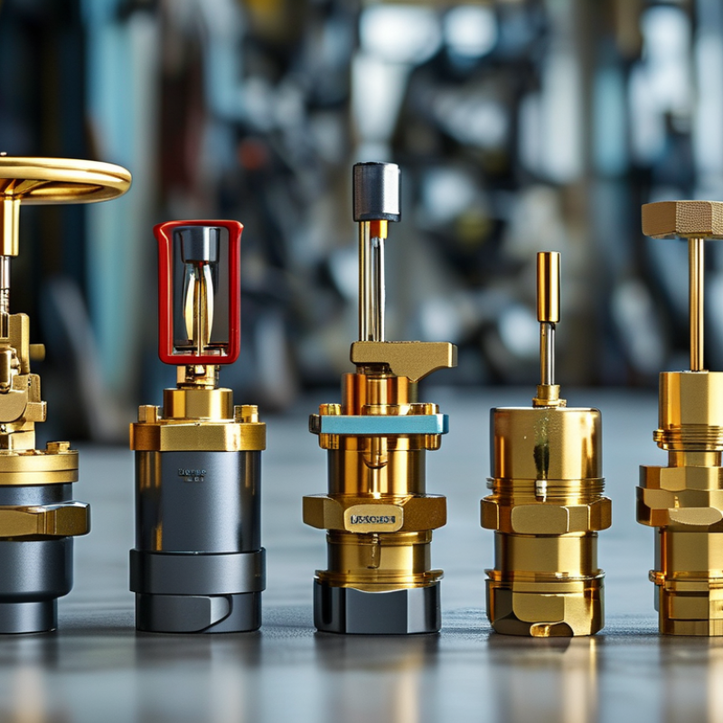
Hydraulic Pressure Relief Valves: Purpose, Types, and Operating Principles
Hydraulic pressure relief valves protect circuits from excessive pressure. They open when system force exceeds a preset spring or pilot setting. Oil then flows back to the reservoir, limiting damage to pumps, hoses, and actuators. In practice, correct sizing matters as much as the pressure setting. A small valve may create heat and unstable control.
Direct-acting valves use a spring-loaded poppet or spool. They react quickly and suit compact, lower-flow systems. Pilot-operated valves use main-stage flow and pilot control for larger capacities. They usually provide steadier pressure, but contaminated oil can affect their response. Proportional relief valves allow electronic adjustment, which helps machines change pressure during different working cycles.
During inspection, technicians should check the rated flow, pressure range, fluid compatibility, port size, and temperature limits. A clean filter supports reliable operation. The valve should be tested near its actual working flow, not only on a bench. Small details matter. I have seen a correct-looking setting fail because a gauge was installed too far from the valve. Pressure losses in long pipes can mislead operators. Installation guidance such as ISO 4413 can support safer design reviews, but site conditions still require professional judgment. A neat pressure chart can mislead. Recheck it.
Top 10 Hydraulic Pressure Relief Valves for Global Buyers? - Hydraulic Pressure Relief Valves: Purpose, Types, and Operating Principles
| Rank | Valve Type | Primary Purpose | Operating Principle | Typical Pressure Range | Typical Flow Capacity | Adjustment Method | Common Applications | Key Buying Considerations |
|---|---|---|---|---|---|---|---|---|
| 1 | Direct-Acting Relief Valve | Protects a hydraulic circuit from excessive pressure. | Inlet pressure acts directly on a poppet or spool. When pressure exceeds the spring setting, the valve opens and diverts fluid to the tank. | Up to approximately 350 bar | Low to medium | Manual screw or knob | Compact power units, clamping systems, mobile equipment, and secondary protection circuits. | Select the correct pressure range, port size, fluid compatibility, and response characteristics. |
| 2 | Pilot-Operated Relief Valve | Controls high flow rates with stable pressure regulation. | A small pilot stage controls pressure above the main spool or poppet, allowing the main stage to handle larger flow with reduced pressure variation. | Approximately 70–420 bar | Medium to very high | Manual, remote, or proportional control | Industrial presses, injection-molding machinery, steel equipment, and large hydraulic power units. | Check minimum flow requirements, pilot-drain configuration, back-pressure limits, and response time. |
| 3 | Sandwich or Modular Relief Valve | Provides pressure protection without separate pipe-mounted plumbing. | The valve is installed between standardized manifold plates and controls pressure in a selected circuit or passage. | Up to approximately 315 bar | Low to medium | Manual screw or tamper-resistant adjuster | Machine tools, compact manifolds, automated production lines, and multi-function hydraulic blocks. | Verify mounting pattern, valve height, flow direction, sealing method, and available installation space. |
| 4 | Cross-Port Relief Valve | Protects actuator ports from shock loads and excessive differential pressure. | One relief element opens when pressure at a working port exceeds its setting and transfers fluid to the opposite port or return line. | Approximately 70–350 bar | Medium | Independent screw adjustment per port | Hydraulic motors, winches, rotary actuators, conveyors, and mobile drive systems. | Compare cracking pressure, full-flow pressure, crossover flow path, and motor braking requirements. |
| 5 | Thermal Relief Valve | Releases pressure caused by fluid expansion in a blocked section. | A small spring-loaded valve opens when temperature-related pressure rises above its low preset threshold. | Typically 10–50 bar | Low | Fixed or limited adjustment | Clamped cylinders, isolated hydraulic lines, mobile machinery attachments, and heat-exposed circuits. | Do not use it as the main pump protection valve; confirm discharge routing and temperature conditions. |
| 6 | Solenoid-Controlled Relief Valve | Enables remote unloading, pressure selection, or emergency pressure release. | An electrically actuated pilot stage changes the pressure-control condition of the main relief valve. | Up to approximately 350 bar | Medium to high | Electrical on/off control | Presses, test benches, automated machinery, accumulator circuits, and safety shutdown systems. | Confirm voltage, connector protection, fail-safe behavior, switching frequency, and manual override options. |
| 7 | Proportional Pressure Relief Valve | Provides electronically adjustable pressure control during changing machine cycles. | A proportional solenoid varies pilot force in response to an electrical command, adjusting the relief pressure continuously within its rated range. | Approximately 50–350 bar | Medium to high | Analog electrical signal | Closed-loop machinery, energy-saving systems, forming equipment, and process automation. | Evaluate command signal, hysteresis, repeatability, electronics compatibility, and heat dissipation. |
| 8 | Cartridge Relief Valve | Offers compact, high-flow pressure protection inside a custom manifold. | A replaceable cartridge element operates within a cavity and uses a spring-loaded poppet or spool to control pressure. | Up to approximately 420 bar | Medium to very high | Fixed, manual, or pilot-adjusted | Custom manifolds, mobile hydraulics, compact power packs, and high-density fluid-control systems. | Check cavity dimensions, insert orientation, sealing materials, contamination sensitivity, and service access. |
| 9 | High-Pressure Water-Glycol Relief Valve | Protects systems using fire-resistant water-based hydraulic fluids. | A spring-loaded or pilot-operated mechanism opens at the preset pressure while materials and seals are selected for water-containing fluids. | Approximately 100–315 bar | Medium to high | Manual or remote adjustment | Fire-risk areas, steel processing, mining, foundries, and selected industrial hydraulic systems. | Verify fluid approval, corrosion resistance, seal compatibility, viscosity range, and leakage limits. |
| 10 | Accumulator Safety Relief Valve | Isolates, protects, and safely depressurizes hydraulic accumulators. | The valve limits accumulator pressure and may incorporate a shutoff, bleed, check, or emergency unloading function. | Up to approximately 350 bar | Medium to high | Manual, solenoid, or integrated control | Emergency power systems, pulsation dampening circuits, energy storage units, and safety-critical machinery. | Check accumulator volume, gas pre-charge, certified pressure rating, discharge capacity, and local safety regulations. |
Related Posts
-
Top 10 Hydraulic Solenoid Valves for Global Buyers?
-
How to Choose the Right Hydraulic Solenoid Valves for Your System?
-
Top Benefits of Using Pump Valves for Efficient Fluid Control
-

Why Choose Automated Valves for Your Industry Needs?
-
Understanding the Importance of Pressure Control Valves in Modern Industrial Applications
-

Ultimate Guide to Mastering Hydraulic Flow Control Techniques for Optimal Performance