skip to Main Content
Choosing C Mount Industrial Lenses is rarely a simple matter of matching a thread size. Global buyers must connect optical performance with cameras, lighting, software, and production conditions. A lens may fit a 1-inch C-mount camera mechanically, yet still create dark corners on the sensor. That small mismatch can weaken inspection accuracy.
Optical engineering educator Dr. John E. Greivenkamp puts the trade-off plainly: “There is no such thing as a perfect lens.” His point matters in factory imaging. Buyers should compare sensor format, focal length, working distance, aperture, distortion, and wavelength response. A 16 mm lens may capture a wide conveyor area, while a 25 mm lens may show smaller defects more clearly. Check the image circle. Then check the edges.
Real conditions often expose overlooked weaknesses. Vibration can reveal loose mounts. Heat can change focus. Glare can hide scratches on polished metal. Lens charts help, but they do not replace testing. Measurements may use different sensors, lighting, or contrast standards. That makes direct comparison imperfect.
Reliable sourcing also requires clear documentation. Request drawings, coating details, operating temperature ranges, test data, and compatible camera recommendations. Confirm thread accuracy and back focal distance before ordering large quantities. Ask about sample evaluation and replacement support. Not every low-cost option is a poor choice, but unverified savings can become expensive downtime.
This guide explains how to assess C Mount Industrial Lenses with practical criteria, careful questions, and realistic expectations. The best selection is not always the sharpest lens. It is the lens that performs consistently in your actual system.
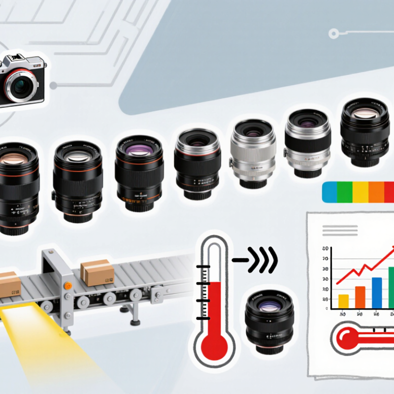
C mount industrial lenses follow a widely recognized 1-inch, 32 TPI thread and a 17.526 mm flange focal distance. These dimensions support interchangeability across many machine vision systems. However, C mount is not a complete optical performance standard. Image circle, distortion, coating, resolution, and working distance still vary considerably. A lens covering a 2/3-inch sensor may fail on a 1.1-inch sensor. Check the sensor diagonal before comparing prices.
In production, I measure the actual field of view at the working distance. A calculator helps, but it cannot reveal glare, vibration, or edge softness. Those problems appear beside the conveyor. According to the International Federation of Robotics World Robotics 2024 report, 541,302 industrial robots were installed globally in 2023. This expanding automation base increases demand for stable inspection optics in packaging, electronics, logistics, and assembly. C mount lenses remain practical because users can replace optics without redesigning the entire camera interface.
Standards reduce mechanical risk, not optical risk. C mount and CS mount are different; CS mount uses a shorter 12.5 mm flange distance. Mixing them can prevent focus or damage equipment. Industrial buyers should request distortion charts, spectral transmission data, tolerance information, and tested sample images. The MarketsandMarkets machine vision report identifies manufacturing inspection and quality control as major market applications, yet reports often group cameras and lenses together. That limitation deserves attention. A projected market figure does not guarantee lens suitability. Test the lens with the final lighting, sensor, and motion speed. Real conditions are less forgiving.
Choosing a C mount industrial lens starts with the imaging requirement, not the camera catalog. The sensor size defines the required image circle. A lens that covers a one-inch sensor may still produce dark corners on a larger sensor. Check this before comparing prices.
Focal length controls field of view and working distance. For example, a 25 mm lens can inspect a moderate area from a short conveyor distance. Measure the target, camera position, and acceptable distortion. Then calculate the needed focal length. Aperture also matters. A wider aperture improves brightness but can reduce depth of field. That trade-off is often underestimated.
Resolution should match the sensor’s pixel size. Review MTF data when available, especially near the image edges. Industrial surfaces reveal weak corner performance quickly. Distortion, back focal length, and C mount thread accuracy also affect installation. For moving lines, shutter speed and available light may require a faster lens. Infrared or ultraviolet imaging needs compatible optical coatings. Do not assume visible-light performance transfers across wavelengths.
Environmental details deserve equal attention. Dust, vibration, temperature changes, and cleaning methods can alter long-term reliability. In practical testing, a lens may perform well on a bench but fail after repeated focus adjustments. That result deserves investigation, not excuses. Ask for tolerance data, test images, and calibration guidance. A specification sheet is useful, but the real scene remains the final judge.
Matching focal length and sensor coverage to your camera prevents costly image failures. A C mount lens may fit physically, yet still produce poor results. The key is matching its image circle with your sensor size.
However, focal length changes field of view, not sensor coverage. Check both specifications carefully. If the image circle is too small, the corners may turn dark.
Black corners. That problem can appear only after installation.
Tips: Measure the sensor’s width and height before selecting a lens. Compare them with the stated image circle. Then calculate the expected field of view using working distance and focal length. Leave a small coverage margin for alignment changes. Confirm the C mount thread and flange distance with the camera manual. Ask for test images from the intended sensor format when possible.
In practical installations, lighting and lens position often reveal hidden weaknesses. A lens may look sharp in a catalog but soften near the edges. I have seen teams choose a longer focal length for detail, then lose too much viewing area. That choice needs review.
Test the lens with your actual sensor, lighting angle, and target surface. Check distortion, corner sharpness, and focus stability at operating temperature. Reliable suppliers should provide measured data, not vague claims. Specifications matter, but real images matter more.
How to Choose C Mount Industrial Lenses for Global Buyers
Choosing a C mount industrial lens starts with compatibility, not focal length. Confirm the camera’s thread specification and flange focal distance, typically 17.526 mm for a C mount. A CS-mount camera may require a different lens position. Check the sensor format carefully. A lens designed for a smaller sensor can leave dark corners on a larger one. The lens image circle should fully cover the sensor, with slight tolerance for production variation.
Mounting stability affects image quality. Inspect thread depth, housing clearance, and locking-ring access before installation. A heavy lens may need additional support, especially on equipment exposed to vibration. Optical performance depends on more than resolution. Compare the required working distance, field of view, distortion, light transmission, and wavelength range. For barcode inspection, edge clarity matters. For measurement, low distortion matters more. Infrared applications need compatible optical coatings. I once overlooked the effect of a protective window; the extra glass changed focus slightly. That detail deserved earlier testing.
Tips: Request a mechanical drawing and test sample when possible. Measure the sensor, thread, and flange distance independently. Use a printed target at the real working distance. Check image corners, not only the center. Test with production lighting. A clear datasheet helps, but it cannot replace a physical trial. Allow adjustment space for focus and aperture. Reflect carefully before final approval.
| Application Category | Typical Sensor Format | Common Focal Length | Recommended Image Circle | Typical Maximum Aperture | Mount Compatibility | Key Optical Performance Check | Selection Guidance |
|---|---|---|---|---|---|---|---|
| General Machine Vision | 1/3-inch to 1/1.8-inch | 8–25 mm | At least 8–9 mm | f/1.4–f/2.8 | C-mount, 1"-32 UN-2A thread | Low geometric distortion, adequate corner sharpness, and stable focus at the working distance | Select a focal length according to the required field of view and camera-to-object distance. |
| Large-Sensor Inspection | 2/3-inch to 1-inch | 12–50 mm | At least 11–16 mm | f/1.8–f/4 | C-mount; verify the lens image circle covers the complete sensor | Edge resolution, illumination uniformity, and absence of mechanical vignetting | A lens designed only for 1/3-inch or 1/2-inch sensors may produce dark corners on larger sensors. |
| High-Speed Imaging | 1/2-inch to 1-inch | 8–35 mm | Sensor diagonal plus safety margin | f/1.4–f/2.8 | C-mount with a secure lock or retaining mechanism where vibration is present | Light transmission, shutter-compatible aperture, low chromatic aberration, and minimal focus shift | Use a larger aperture when short exposure times are required, but check depth of field and aberration control. |
| Telecentric Measurement | Commonly 1/2-inch to 2/3-inch | Application-specific | Must cover the sensor diagonal | Often f/4–f/8 | Some telecentric systems use C-mount camera interfaces; confirm flange and clearance requirements | Telecentricity, measurement distortion, working distance, and depth of field | Do not substitute a standard C-mount lens when object-size accuracy and perspective control are required. |
| Low-Light Monitoring | 1/2-inch to 1-inch | 6–50 mm | At least the sensor diagonal | f/1.0–f/2.8 | C-mount; check iris control and filter-thread clearance | Relative illumination, flare resistance, contrast at maximum aperture, and near-infrared transmission if applicable | Stopping down can improve sharpness, but it reduces incoming light and may require longer exposure. |
| Near-Infrared Imaging | 1/2-inch to 1-inch monochrome or extended-response sensor | 8–35 mm | At least the sensor diagonal | f/1.4–f/4 | C-mount; confirm performance over the intended wavelength range | Focus shift between visible and near-infrared wavelengths, transmission at 850 or 940 nm, and chromatic correction | Use a lens with specified near-infrared performance rather than assuming visible-light specifications will apply. |
| Wide-Field Area Coverage | 1/3-inch to 2/3-inch | 2.8–8 mm | At least 6–11 mm | f/1.4–f/2.8 | C-mount; verify rear-element clearance and camera housing compatibility | Distortion, corner illumination, field curvature, and minimum object distance | Short focal lengths provide a wider field of view but generally require closer attention to barrel distortion. |
| Long-Working-Distance Inspection | 1/2-inch to 1-inch | 35–100 mm | At least the sensor diagonal | f/2.8–f/5.6 | C-mount if the lens rear thread and camera flange specifications match | Resolution at the required working distance, focus travel, depth of field, and vibration resistance | Longer focal lengths narrow the field of view and can help maintain a greater camera-to-object distance. |
Mounting reference: A standard C-mount uses a 1-inch diameter, 32-thread-per-inch mounting thread and has a nominal flange focal distance of 17.526 mm. C-mount and CS-mount commonly share the same 1-inch, 32-thread interface, but CS-mount cameras use a shorter 12.5 mm flange focal distance. A C-mount lens normally requires a 5 mm spacer or adapter when used on a CS-mount camera. Always verify thread type, flange distance, sensor coverage, rear clearance, and camera housing dimensions before purchase.
How to Choose C Mount Industrial Lenses for Global Buyers
Selecting a C mount industrial lens requires more than comparing catalog prices. Supplier reliability matters when production crosses borders. Request company records, manufacturing locations, quality certificates, and recent inspection reports. A clear response usually reveals operational discipline. An attractive website does not prove consistency.
Ask for measured data, not only design claims. Check resolution, distortion, relative illumination, working distance, and sensor coverage. Test samples under your actual lighting and camera conditions. Small focus shifts can appear after temperature changes. Review coating performance, mechanical tolerances, and mount dimensions. Keep test images and measurement records. They support fair supplier comparisons. Sometimes, the cheapest sample performs well. Larger batches may differ. That possibility deserves attention.
Global purchasing adds practical risks. Confirm minimum order quantities, production lead times, packaging methods, and replacement procedures. Request export documents, product classifications, and written warranty terms before payment. Clarify Incoterms and responsibilities for damaged shipments. A supplier should explain how it manages traceability by batch or serial number. This helps when a lens fails months later. Communication speed also matters across time zones. However, fast replies can hide weak technical knowledge. Ask precise questions and compare the answers with test results. A small pilot order is often wiser than a large commitment. Mistakes still happen, even with careful evaluation. Record them, revise the checklist, and keep improving the purchasing process.
